Table of Content
This is about a 2-hour recording and can be done from home. Work with the client to translate project requirements, and ensure schedules and budgets stay on track using standard management methodology. Lead project team members, and provide ongoing feedback, supporting them in their efforts to meet project goals.

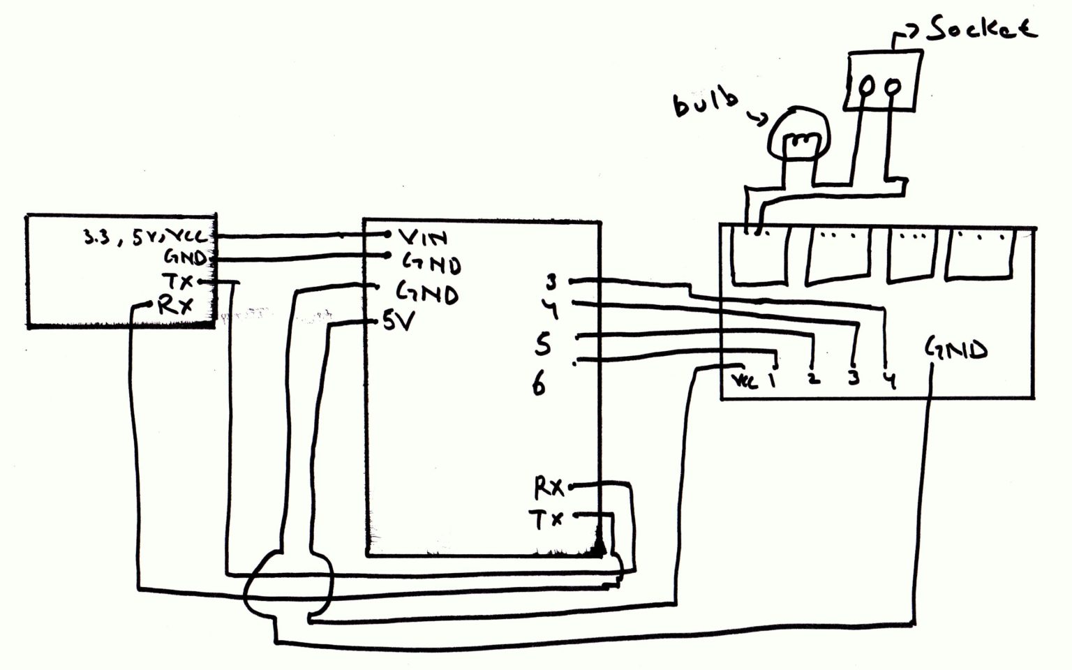
We can connect AC devices to the output terminals of those relays. First connect one wire of the AC source with the common terminal of all relays and the second wire of AC source to one terminal of AC devices. Then connect the other terminal of AC devices to the NO terminal of relays. Microcontroller is a compact integrated circuit designed to govern a specific operation in an embedded system. A typical microcontroller includes a processor, memory and input/output (I/O) pe...integrated circuit designed to govern a specific operation in an embedded system.
How to make a Digital Watch using an 0.96 inch OLED Display
Next, add a horizontal arrangement next to each label, and drag 2 buttons into each horizontal arrangement. First, add all the non-visible components - the speech recognition, the Bluetooth client, and the notifier. Needs to review the security of your connection before proceeding.
Instead, we send the interpretations of the voice commands to the Blynk App which in turn sends it to the NodeMCU. To make Google Assistant understand the voice commands we make, IFTTT has to be used. 'New Project' to create a new project and then name it according to your wish. Select the hardware device as NodeMCU and connection type as WiFi, while creating the project.
Other jobs related to home automation using arduino block diagram
The ground of both GSM and Arduino should be connected with each other otherwise system will not work properly. Andrelaysare connected to digital pin 10, 11, 12 of Arduino for controlling light 1, light 2, TV respectively using ULN 2003 IC. ULN2003 is a high-voltage high-current Darlington transistor arrays. Each consists of seven NPN Darlington pairs that feature high-voltage outputs with common-cathode clampdiodesfor switching inductive loads. And 5 volt relays are used here, which are best suitable for these types of Projects.

The project consists of a 16×2 LCD module for displaying the status of the home appliances. The status of the connected devices can be changed by sending an SMS from your mobile phone. Upon receiving SMS commands through GSM module, arduino will change the status (turn ON/OFF) of the device that is mentioned in the SMS. GSM module’s pin Tx and Rx is directly connected with Rx and Tx pins of Arduino. And power supply adaptor is also connected with GSM module.
4x4 RGB LED Cube
A typical microcontroller includes a processor, memory and input/output (I/O) peripherals on a single chip. They are essentially simple miniature personal computers designed to control small features of a larger component, without a complex front-end operating sy... When we again Press the App “Button 1“, but this time the app sends Load value “A” to the Bluetooth module. Again the Arduino gets this value through the Bluetooth module. But this time the Arduino sends a High input voltage to the Input-1 pin of the relay module.
Save the JQuery library file as the jquery.min and the full name of the file will be “jquery.min.js”. Let’s begin to build our project – GSM Based Home Automation Using Arduino. The source code is present at the end of the video. First of all, open the Play Store of your Android Smartphone and search for “Bluetooth Control for Arduino”. Arduino 5V Pin, but LCD Display LED + Pins connected to Arduino 5V Pin through 220ohm resistor.
Here ‘0’ means to turn on, so we are basically saying Blynk to turn on arelay that is connected to pin D3, which in our case is Relay one. So, as we assigned the Digital Pin D3 of NodeMCU to relay one we must write D3 in place of “DigitalPinToBeUpdateHere”. Select the card that says “Say a simple phrase”. Type in the phrases you want Google Assistant to understand as the command. In our case, that could be "Turn on the bulb.", "Turn on relay 1", etc.

At the same time, you can also see the LED on the Bluetooth Module is blinking with some delay. It means your Bluetooth is successfully connected. While we used a single relay in this example, you can easily expand your system by using a multi-channel relay module. 3) Once you select the device, you’ll be connected to the HC-05 transceiver. The app will now prompt you to enter the mode that you wish to use.
At the end you need to accumulate data for each specified country and each date . Then you need to call create_plot() function, provided to you ,to create a chart (). Once all these steps are done, our registered voice commands can be used to turn on and off the electrical/electronic appliances connected to the NodeMCU. Four electronic appliances can be connected since we're using 4 Relay pins but in our case, we only used one, an LED bulb. Another section of the circuit is the interfacing of Arduino to 16×2 LCD.
When possible, we might share with Facebook information like name, email, phone, address. Facebook Advanced Matching can improve ads attribution and conversion tracking. It can help us reach better-targeted custom audiences through our ads. When possible, we will share with Facebook hashed information like your name, phone, email, or address. In order to that, you’ll need to download the Arduino Bluetooth Controller app on your Android device. Simply unplug the jumper wire connected to Pin 0 on the Arduino UNO , and re-attempt the code update.
And, connect Tx and Rx pins of Bluetooth module to Rx and Tx pins of Arduino Uno, respectively. Pin 2 of Arduino Uno is connected to T1 through base current-limiting resistor R1. Similarly, pins 3 and 4 of Arduino Uno are connected to T2 and T3 through R3 and R5, respectively. When the App successfully connects to the Bluetooth Module, Then you can see the blue light on the “Connection button“.
CircuitsToday.com is an effort to provide free resources on electronics for electronic students and hobbyists. Our webiste has thousands of circuits, projects and other information you that will find interesting. Display status of the devices in an LCD using a 16×2 LCD module. Change the status (turn ON/OFF) of the device upon receiving commands through SMS. Next, open the app and pair Bluetooth module HC-05 with the Bluetooth of your smartphone.
After that we will initialize pins to which we will connect relays as output pins. Then we will configure ESP8266 in access point mode. Arduino + ESP8266 is programmed as a web server such that we can control those relays through a web browser. Connect three relays to pins 11, 12 and 13 of the Arduino.


No comments:
Post a Comment