Table of Content
CH_PD is Chip Power Down pin, which is active low. So we will give 3.3V to it, which will enable the chip. Then connect the TXD pin of the ESP8266 with the digital pin 2 of the Arduino. Then make a voltage divider to make 3.3V for the RXD of the ESP8266 which is connected to the pin 3 of Arduino. Here we are using software UART through digital pins 2 & 3 of Arduino.
Next, make a function to auto-connect to the HC-05 Bluetooth module when the screen is initialized. If the connection is successful, we show an alert, saying that the connection was successful. Make a table arrangement with 3 rows, and add a label to each row, for individual lights. Hi Kurian G., I noticed your profile and would like to offer you my project. I would like my logo to be my name Sylvia Dorrance with the addition of Home Selling Team placed underneath my name. My name should be in a larger font size then Home Selling Team.
Objectives of the Project
The ultimate aim of this project is to be able to use our voice to control electronic home appliances like TVs, lights, fans, etc. In our case, we decided to demonstrate the idea using Google voice assistant and an LED bulb. ESP8266 – Arduino Web Server – IP AddressFirst connect your system to the access point created by ESP8266 module . Update the IP address in the control.html file created above. Now you can control your home appliances very easily.

The library replicates hardware functions and handles the task of serial communication. This will help the programmer to use hardware serial pins for debugging purpose. For this application we’re using a relay module which includes the relay drive circuit allowing it to connect directly to a microcontroller GPIO pin.
How to make a Digital Watch using an 0.96 inch OLED Display
Next, add a horizontal arrangement next to each label, and drag 2 buttons into each horizontal arrangement. First, add all the non-visible components - the speech recognition, the Bluetooth client, and the notifier. Needs to review the security of your connection before proceeding.
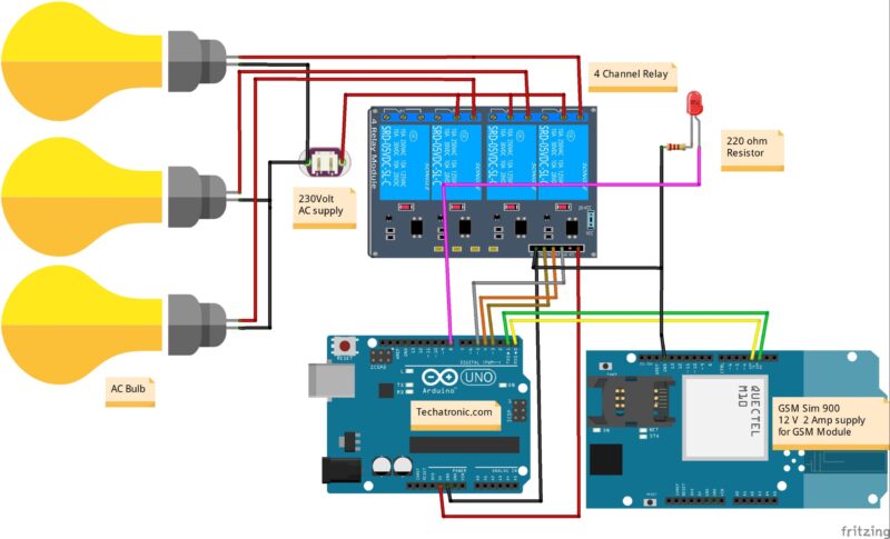
JHD162A is a 16×2 LCD module based on the HD44780 driver from Hitachi. The JHD162A has 16 pins and can be operated in 4-bit mode or 8-bit mode . Connect NO terminal of each relay to one terminal of electrical load, and the other terminal of the load to neutral line of 220V AC mains power supply. Connect live line 220V to COM terminal of each relay. And in TV ON string is match with name string then TV will turn ON and GSM sends back a notification message like TV ON. Using the above setup, you can turn any device into a smart device that can be controlled from your smartphone.
Circuit Diagrams
And, connect Tx and Rx pins of Bluetooth module to Rx and Tx pins of Arduino Uno, respectively. Pin 2 of Arduino Uno is connected to T1 through base current-limiting resistor R1. Similarly, pins 3 and 4 of Arduino Uno are connected to T2 and T3 through R3 and R5, respectively. When the App successfully connects to the Bluetooth Module, Then you can see the blue light on the “Connection button“.
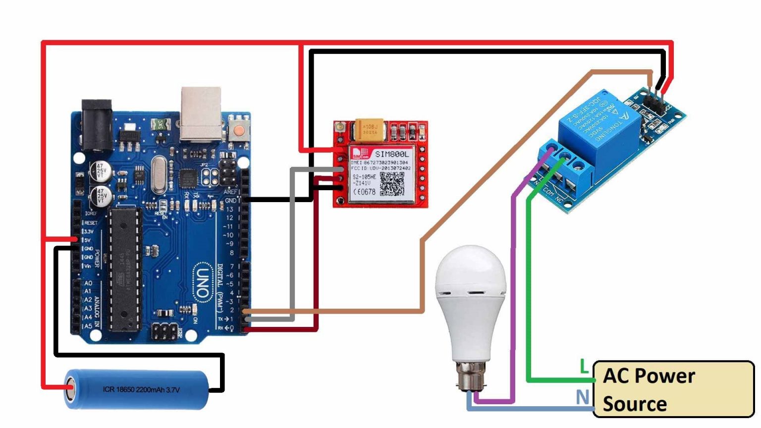
At the same time, the “D1 is ON” status print on the 16×2 LCD Display Module. The communication between GSM module and arduino is serial. So you have to disconnect wiring in Rx and Tx each time you burn the program to Arduino. Once the program is loaded successfully, you can reconnect these pins and have the system working.
Arduino Tutorial #7 – LED Brightness Control Using Potentiometer
This is about a 2-hour recording and can be done from home. Work with the client to translate project requirements, and ensure schedules and budgets stay on track using standard management methodology. Lead project team members, and provide ongoing feedback, supporting them in their efforts to meet project goals.
You will get the app on your phone as shown in Fig. Relay connections marked as x, y, COM , NO and NC are shown in Fig. X and y are two points across the coil of the relay. In programming some string are defined for comparing. Light 1 is connected with relay 1, light 2 is connected with relay 2 and TV is connected with relay 3.
When possible, we might share with Facebook information like name, email, phone, address. Facebook Advanced Matching can improve ads attribution and conversion tracking. It can help us reach better-targeted custom audiences through our ads. When possible, we will share with Facebook hashed information like your name, phone, email, or address. In order to that, you’ll need to download the Arduino Bluetooth Controller app on your Android device. Simply unplug the jumper wire connected to Pin 0 on the Arduino UNO , and re-attempt the code update.
You should now be able to update the code successfully. After programming is complete then reconnect the jumper wire. The relay module we’re using can handle up to 10 amps of current at up to 240V AC.


No comments:
Post a Comment